Tiny Turbines, Big Problems: Taming Micro Wind Turbine Vibrations
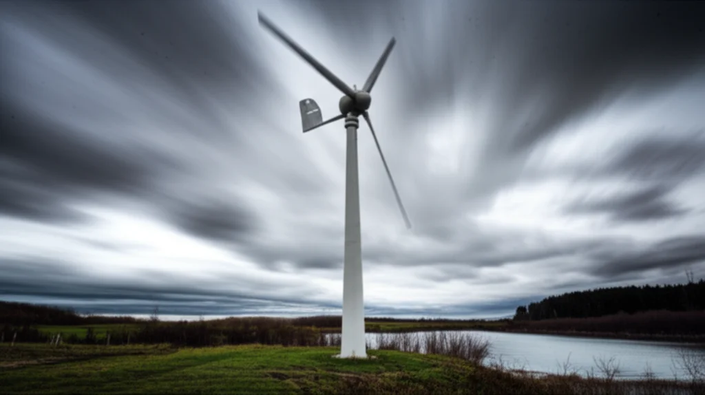
Hey there! Let’s chat about something pretty cool but also a bit shaky: micro wind turbines. You know, those smaller ones you might see providing power off-grid or for a single home? They’re fantastic for bringing clean energy to places where big wind farms just aren’t practical or economical. But here’s a little secret: these smaller guys, typically 10 kW or less, can get seriously buzzy. We’re talking high vibration levels compared to their giant cousins.
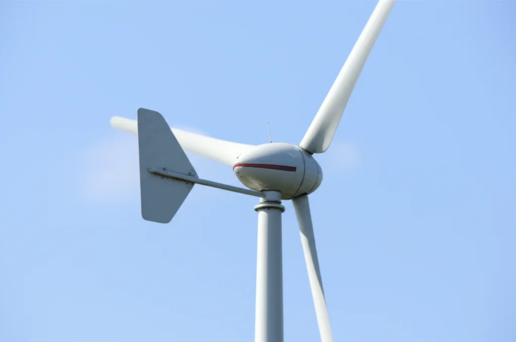
Why all the shake, rattle, and roll? Well, they spin *fast*. Like, really fast. To keep things simple and cost-effective, they often ditch the heavy gearbox you find in large turbines and bolt the blades right onto the generator. Plus, instead of fancy active yaw systems that constantly motor the turbine into the wind, they often use a simple tail vane. Now, while that tail vane is great for pointing the turbine in the right direction, unpredictable wind shifts can make it whip around pretty quickly, leading to high yaw rates.
Combine those high rotational speeds with sudden, high yaw rates, and you get some serious gyroscopic loads. Think of it like spinning a bicycle wheel and then trying to twist it – there’s a strong resistance force perpendicular to your twist. On a micro turbine, this means when the tail vane yaws the turbine, the rotor wants to pitch up or down. This unique cocktail of dynamic loads is a big deal for these small machines.
The tricky part is, most of the sophisticated software and research out there is built for the big leagues – utility-scale turbines. Their dynamics are different. So, diving deep into the specific dynamics of micro wind turbines is essential. That’s exactly what we set out to do in this study.
Unpacking the Micro Turbine Puzzle
We wanted to understand *why* micro turbines behave the way they do dynamically. Instead of relying solely on complex numerical simulations, which are great but can sometimes feel like a black box, we decided to build a simple mathematical model. Why simple? Because simple models can often give you clearer insights into the fundamental physics at play. They help you see the forest for the trees, so to speak.
Our model focuses on the peculiar setup of micro turbines: the direct drive to a permanent magnet generator (PMG) and the passive tail vane yaw system. These features, as we mentioned, lead to high rotational speeds and potentially high yaw rates, which in turn generate significant gyroscopic loads. These loads can stress the main shaft and contribute heavily to vibrations.
Existing research has looked at turbine blades extensively, and some studies have touched on structural health monitoring for small turbines, even noting how things like temperature can affect vibrations. Gyroscopic moments have been studied for large turbines, showing how they can influence system frequencies and critical speeds. But specific, detailed dynamic studies for the *whole structure* of micro turbines, considering their unique design, have been less common.
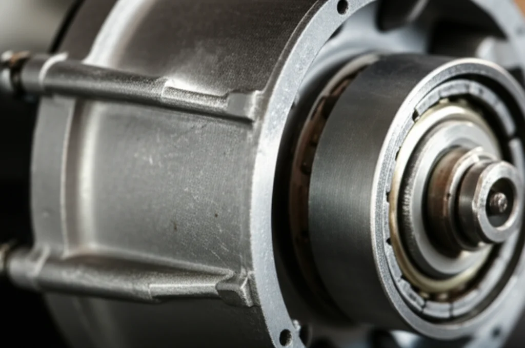
The use of outer rotor generators in μWTs is another key difference. They simplify construction by letting you attach the blades directly to the generator casing. But, mechanically, the bearings supporting the rotor often have a small span relative to the rotor’s diameter. This can lead to excessive rotor vibrations, which are bad news. Excessive vibrations mean:
- Reduced performance and less power output.
- Fatigue and damage to structural parts.
- A shorter overall lifespan for the turbine.
So, given that large turbine research doesn’t directly apply, and most design software isn’t tailored for μWTs, there’s a real need for dedicated studies like ours.
Building Our Simple Model
To get a handle on these vibrations, we developed a mathematical model using a lumped parameter system. Think of it as simplifying the complex turbine structure into a few key masses connected by springs and dampers. We focused on the main components: the rotor (blades plus generator), the tower, and the tail vane.
Our model accounts for six degrees of freedom – basically, the key ways the turbine can move and shake:
- Two for the rotor’s side-to-side and up-and-down movement (translation).
- Two for the rotor’s tilting (pitching) and twisting (yawing) rotation.
- One for the tower’s side-to-side movement.
- One for the tail vane’s side-to-side movement.
We considered two primary forces driving these vibrations: centrifugal forces due to any imbalance in the rotor (which is super common) and the fluctuating aerodynamic forces caused by the tower shadow effect. Tower shadow happens because the wind slows down just before it hits the tower. As a blade passes through this slower patch, the force on it drops, creating a pulsing load.
Centrifugal forces are pretty straightforward: if the rotor’s center of mass isn’t exactly at the center of rotation, it creates a force proportional to the mass, the eccentricity (how far off-center it is), and the square of the rotation speed. This force pulses once per revolution (what we call the 1p frequency).
Tower shadow is a bit more complex. As each blade passes behind the tower (or in the tower’s “shadow” upwind), the wind speed drops. This causes the aerodynamic forces (lift and drag) on the blade to fluctuate. For a three-bladed turbine, this happens three times per revolution, creating a pulsing load at the 3p frequency. Because the wind speed variation isn’t perfectly smooth, you also get harmonics at 6p, 9p, and so on.
We used Lagrange’s method (a classic physics technique) to derive the equations of motion for our simplified system. This gave us a set of six differential equations describing how the turbine moves based on its mass, stiffness, damping, and the forces acting on it. We then solved these equations using numerical methods to see how the turbine vibrates under these forces.
Putting Our Model to the Test (Verification)
So, how did we know our simple model was any good? We compared its predictions to results from previous studies, specifically experimental and numerical data on tower vibrations from Castellani et al. (2022). Their work used the FAST simulation tool (developed at NREL) and validated it against real-world measurements.
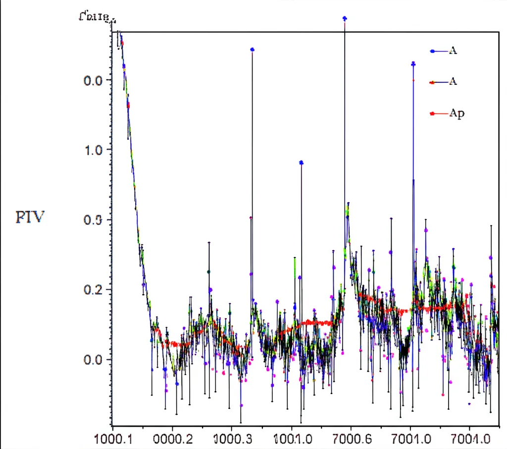
When we looked at the frequency spectrum of the vibrations predicted by our model, we saw exactly what we expected. There were strong vibrations at the 1p frequency, clearly driven by rotor unbalance. And there were significant vibrations at the 3p frequency and its multiples (6p, 9p), which our model correctly attributed to the tower shadow effect. This matched the patterns seen in the experimental data.
We tuned one parameter in our model – the rotor eccentricity (how off-center the mass was) – to match the amplitude of the main 1p vibration component from the FAST/experimental data. Once that was matched, we compared the relative amplitudes of the other frequency components (like the 3p, 6p, 9p). Our model showed good agreement with the ratios seen in the published data, preserving the essential physics of the real turbine’s response.
Of course, there were some differences. Maximum amplitudes can be sensitive to damping values, which weren’t fully detailed in the experimental work. Also, our simple model didn’t account for blade deflection. In reality, when blades bend, they can get closer to the tower, making the tower shadow effect even stronger. These factors likely contribute to the minor deviations, but overall, the model proved capable of predicting the *proportionality* of vibrations at different frequencies with reasonable accuracy.
Playing with the Design Levers (Parametric Study)
With a verified model in hand, we could start playing “what if.” We conducted a parametric study to see how changing key design parameters would affect the turbine’s vibrations. We focused on two things that designers can actually influence:
- The span between the generator’s bearings (`Lr`).
- The position of the rotor’s center of gravity (CG) along the rotor axis (`a*`, which is the distance from the front bearing to the CG, divided by the bearing span).
We kept the rotor’s rotational speed constant at a typical operating speed, as the effect of speed on vibrations (especially near critical speeds) is already well-known.
The results were pretty insightful. We found that increasing the bearing span (`Lr`) generally *decreased* the root mean square (RMS) value of the vibrations, especially the angular ones (pitching and yawing) and the vertical translation. Think of it like spreading your feet wider for better stability – a wider bearing span provides more rotational stiffness, making the rotor less prone to tilting and wobbling. However, it didn’t significantly affect the vibrations in the direction of the wind (the x-direction), as the forces in that direction are transmitted differently.
Next, we looked at shifting the rotor’s center of gravity (`a*`). This parameter had a more nuanced effect. While it didn’t drastically change all vibrations, it significantly impacted the rotor’s translational movements, particularly the vertical vibration (`yR`) and the related pitching (`θx`). We discovered there was an *optimal* position for the CG that minimized the vertical vibration. This minimum occurred when the CG was located at about 65.5% of the distance from the front bearing towards the rear bearing (`a* = 0.655`). Shifting the CG further or closer than this point actually increased these specific vibrations.
This happens because the centrifugal force due to unbalance and the forces transmitted through the bearings interact in a complex way depending on the CG’s position. At the optimal point, these forces balance out in a way that minimizes the net force causing vertical movement.
Applying the Findings (Case Study)
To show the practical value of our model and findings, we applied them to a real-world example: a 1 kW micro wind turbine designed at Ain Shams University, which competes in the International Small Wind Turbine Contest. This turbine had a standard design with parameters similar to our model’s baseline.
Based on our parametric study, we proposed two modified designs for the generator, focusing on increasing the bearing span and optimizing the CG position. We chose a significantly larger bearing span (within practical limits) and two CG positions: one near the optimal point we found (`a* = 0.655`) and one at the end of the span (`a* = 1`), representing the range of possibilities.
We ran our model with the parameters of the original turbine and the two modified configurations. The results were quite impressive! For the first modification (increased span and optimal CG position), the acceleration amplitudes of the rotor’s angular movements (pitch and yaw) decreased by *more than 50%* compared to the original design. The vertical vibrations also decreased significantly.
The second modification (increased span but CG at the end) also reduced angular vibrations, but it actually *increased* the vertical vibrations compared to the optimal CG position, highlighting the importance of getting that CG placement right. Vibrations in the direction of the wind were only slightly affected, as predicted by our parametric study.
This case study clearly demonstrated that by using our simple model to guide design choices for the bearing span and CG position, we could achieve a substantial reduction in vibrations. But that’s not all the model can do. It can also predict the dynamic forces transmitted to the bearings.
Why is this important? Bearings are often the first components to fail in a wind turbine, especially with high vibrations and loads. Knowing the forces they experience allows designers to select more appropriate bearings or predict their lifespan with much greater accuracy. Our model showed that the modifications we proposed significantly decreased these bearing forces, which would directly translate to a longer lifespan for the generator and the entire turbine.
It’s worth noting that many micro turbines have their CG closer to the front bearings (`a*` is small). This is often just a consequence of how the rotor blades add mass out front. Our study strongly suggests that designers should make an effort to shift the CG closer to the middle of the bearing span (around 50-60% seems like a good target based on our findings, with 65.5% being optimal for vertical vibrations in our specific example). This seemingly small change could have a big positive impact on the turbine’s reliability and longevity.
Wrapping It Up
So, what’s the big takeaway here? Micro wind turbines are cool, but they face unique dynamic challenges, especially high vibrations driven by their high speed, passive yaw, and specific generator design. Existing tools and research often fall short because they’re built for larger machines.
We’ve shown that a relatively simple mathematical model, like the one we developed, can be incredibly powerful. It captures the essential dynamics of micro turbines, including the effects of rotor unbalance and tower shadow. Unlike complex numerical simulations, our analytical model provides clear insights into *why* vibrations occur and how design parameters influence them.
Our study highlighted two key design levers: increasing the bearing span and carefully positioning the rotor’s center of gravity. Both can lead to significant reductions in vibrations and bearing loads, ultimately improving performance and extending the turbine’s life. We even showed how applying these findings to an existing turbine could cut vibrations by over 50% in some areas.
While our model is simplified (it doesn’t include everything, like blade flexibility), its ability to accurately predict vibration patterns and bearing forces with minimal computational effort opens up exciting possibilities. It gives designers a valuable tool to make better decisions early in the design process, helping build more robust and efficient micro wind turbines. It’s a step towards giving these tiny powerhouses the specific engineering attention they deserve!
Source: Springer