Nature’s Strong Bond: Kenaf, Sawdust, and Adhesive Joints Under Pressure
Hey there! Let’s chat about something pretty cool that’s happening in the world of materials and how we stick them together. You know how we used to just bolt and rivet everything? Well, these days, adhesives – fancy glue, basically – are becoming the go-to for joining stuff, especially in structures like buildings and vehicles. Why? Because they spread the stress out nicely, they don’t rust like metal fasteners, and they don’t add a ton of weight. Plus, you get a nice smooth finish.
But, like anything, it’s not all sunshine and rainbows. Glued joints can be tricky to take apart if you need to inspect them, and things like heat and humidity can mess with their strength. Also, the surfaces you’re gluing need some prep work to get a really strong bond. And here’s a big one: how you design the joint really matters. Some designs, like the simple ‘single lap joint’ where two pieces overlap, can bend awkwardly under load, causing stress points. That’s where the ‘double lap joint’ comes in – it’s much better at handling those bending issues and keeping things straight.
Why Natural Fibers?
Now, let’s talk about the materials themselves. For ages, we’ve relied on synthetic fibers like glass or carbon to beef up plastics and make composites. They’re strong, sure, but they can be pricey, heavy, and not exactly eco-friendly. This is where natural fibers step onto the stage! Think kenaf, sawdust, jute, flax – stuff that grows right out of the ground. They’re cheap, lightweight, biodegradable, and easier on the machinery when you’re making stuff. Kenaf, in particular, is a bit of a superstar – it grows fast, needs minimal fuss, and has decent mechanical properties.
And sawdust? It’s basically wood waste, readily available and super cheap. Using it in composites is a fantastic way to turn trash into treasure. Imagine making structural panels that, when they’re finally done, you could potentially compost! That’s pretty neat, right?
So, we’ve got these cool natural fiber composites – Kenaf Fiber Reinforced Polymer (KFRP) and Sawdust Reinforced Polymer (SDRP). If we want to use them in real-world structures, we absolutely need to know how to join them reliably. While folks have looked at single lap joints with natural fibers, the double lap joint, which is arguably better for structural loads, hasn’t gotten as much love, especially when joining *different* types of natural fiber composites like KFRP and SDRP. That’s exactly what we decided to dive into.
What We Did: The Experiment
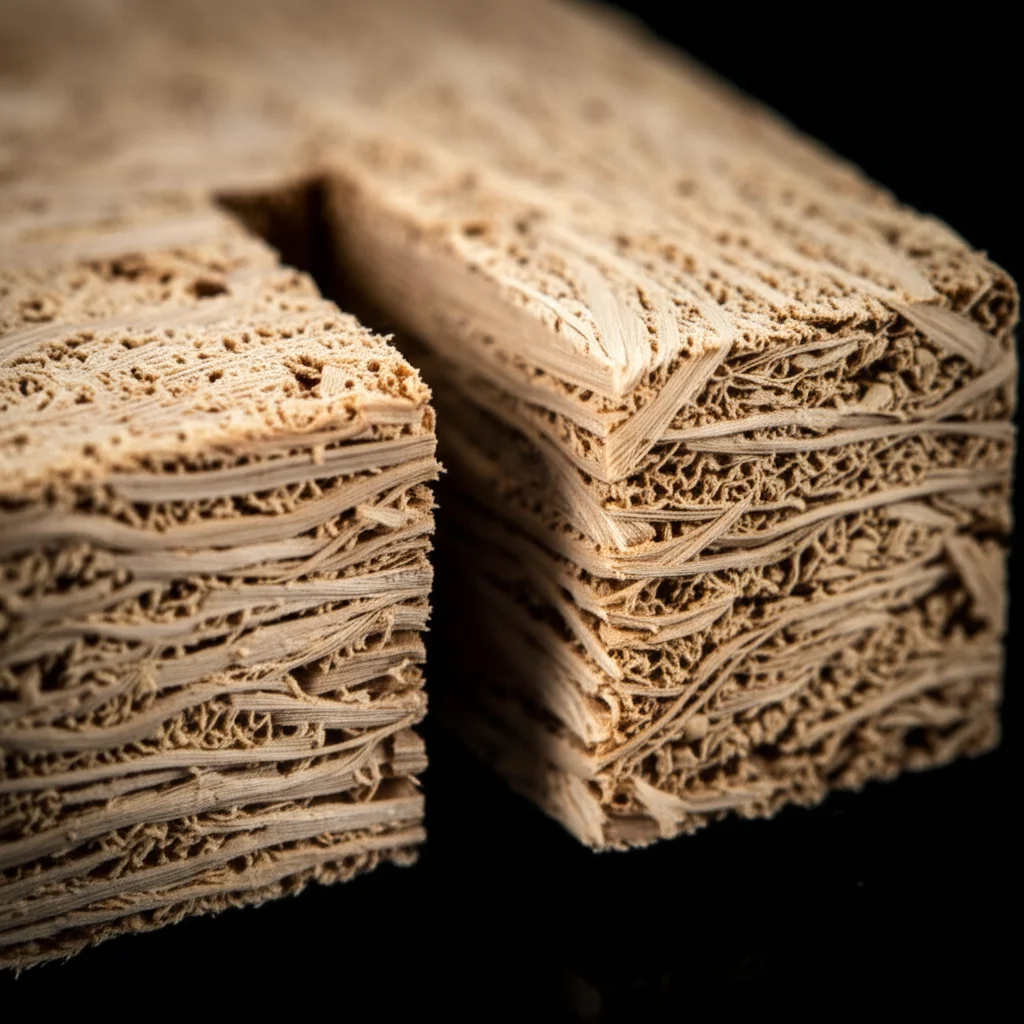
Our mission was to really understand how double lap joints made from KFRP and SDRP behave under compression – basically, pushing them together until they break. We made our own KFRP panels using unidirectional kenaf fibers (about 40% fiber by weight) and SDRP panels with randomly arranged sawdust (about 20% sawdust by weight), both mixed with polyester resin.
Making the panels was a bit of a process. For the KFRP, we carefully laid out the kenaf fibers in a mold, poured in the polyester resin and catalyst mixture, rolled it to make sure the resin got everywhere, and then pressed it and let it cure. The SDRP was similar, but we used sawdust powder and mixed it thoroughly with the resin before pouring. Both panels got a post-cure bake in an oven to really set the resin.
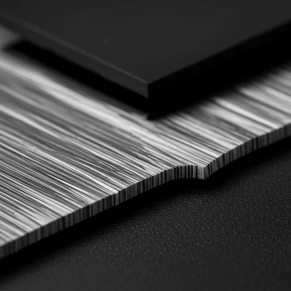
Then came the joint making. We cut the KFRP and SDRP panels into the right shapes for double lap joints. Crucially, we had to prepare the surfaces where the glue would go. We roughed them up with sandpaper – this helps the adhesive grab on better – and then gave them a good wipe-down with acetone to get rid of any gunk. We used a polyester adhesive for the bond, keeping the glue line thickness consistent with a neat little wire insert trick. We made lots of different joints, varying the overlap length (how much the pieces overlap) and the width of the joint.
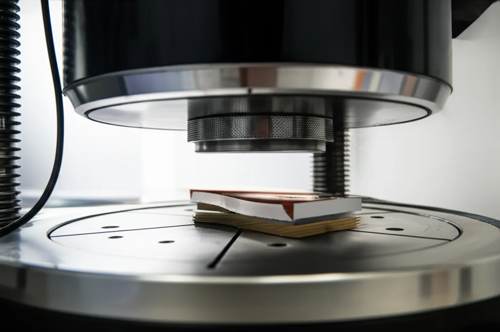
Once the joints were assembled and cured (another oven bake for good measure), it was time for the main event: testing! We put the joints in a big testing machine and pushed them together at a steady speed, recording how much force they could take and how much they compressed until they failed. We tested at least three identical joints for each configuration to make sure our results were reliable.
We also did some standard tests on the KFRP and SDRP materials themselves (tensile tests) to know their basic properties – how strong they are when you pull on them, how much they stretch, etc. This data is super important for the computer modeling part.
Bringing in the Computers: Numerical Analysis
Doing experiments is great, but sometimes you want to see *inside* the material, to understand *why* it breaks where it does. That’s where Finite Element Method (FEM) comes in. It’s a powerful computer tool that lets us build virtual models of our joints and simulate what happens when we apply a load.
We built 3D models of our double lap joints in a software called ABAQUS, using the material properties we found from our tensile tests. We told the computer how the joints were supported and where the load was applied, just like in our physical tests. We used special elements called ‘cohesive elements’ in the adhesive layer – these are designed to simulate how the glue behaves, including when it starts to fail.
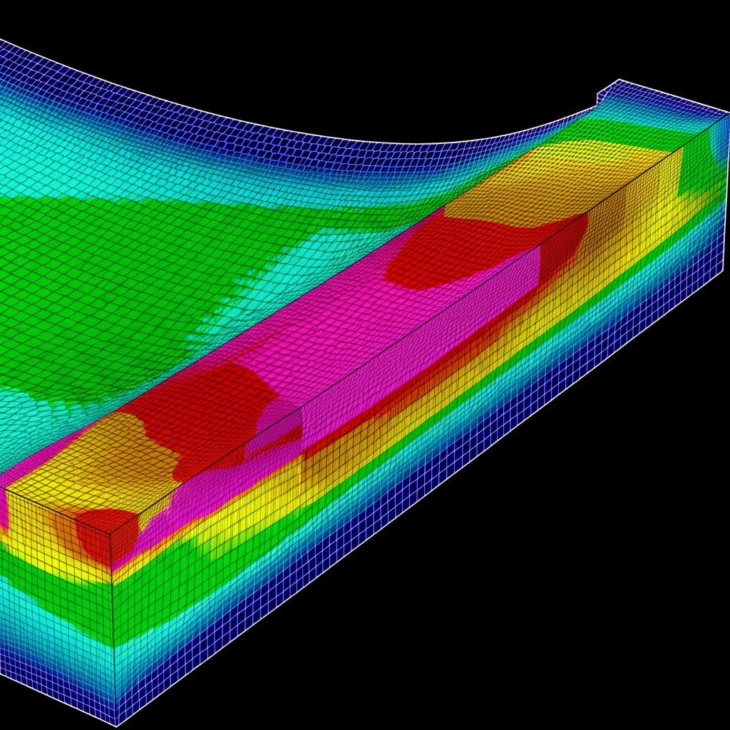
The computer models helped us visualize things like stress distribution – where the forces are highest in the joint. We looked at ‘von Mises stress’ (a general measure of stress) and also specific ‘shear stress’ (forces trying to slide the layers apart) and ‘peel stress’ (forces trying to pull the layers apart).
What We Found: Experimental Results
So, what did all this pushing and computing tell us?
First off, looking at the load-displacement curves from the experiments (how much force vs. how much the joint squishes), most joints started off pretty stiff and linear. Then things got a bit wiggly in the middle before stiffening up again right before failure. Then, *bam!* – a sudden, brittle break. This suggests the adhesive has a bit of elastic-plastic behavior before giving way.
We found that increasing the overlap length generally increased the total load the joint could handle. More glue area means more capacity, right? Makes sense. However, and this is interesting, the *shear strength* (the load divided by the bonded area) actually *decreased* as the overlap got longer. This is likely because the stress isn’t perfectly uniform across the overlap – the edges are doing most of the work, and the middle isn’t pulling its weight as much in longer overlaps.
Increasing the bond width also increased the load-carrying capacity and how much the joint could displace before failing. In fact, for the same total bonded area, increasing the width seemed to be a bit more effective at boosting load capacity than just making the overlap longer.
We saw three main ways the joints failed:
- Adhesive failure: The glue peeled right off the surface of one of the composite pieces. Not ideal, suggests a weak bond to the material.
- Cohesive failure: The glue itself broke, splitting down the middle. This is generally considered a sign of a good bond to the materials – the glue is the weakest link, not the interface. This was the most common failure mode we saw.
- Adherend failure: The composite material itself broke before the glue did. This is the gold standard! It means the adhesive joint is stronger than the materials it’s joining, making full use of their strength. We saw this in one of the largest joints.
Increasing overlap length and bond width also increased the energy the joint could absorb before failure, which is a good thing for structural applications where you might have impacts.
What We Saw: Numerical Insights
The computer models were super helpful for understanding *why* things happened. The stress distribution plots clearly showed that the highest stresses – both shear and peel – were concentrated right at the edges of the overlap area. This stress concentration is like a weak point where damage starts.
As the load increased in the simulation, the area of high stress grew, showing how the failure progresses from the edges inward. The shear stress distribution across the overlap was kind of parabolic, peaking at the ends and dipping in the middle. As we made the overlap longer, the peak shear stress at the ends actually decreased, which helps explain why the total load capacity goes up. But because the stress reduction isn’t perfectly proportional to the length increase, the average shear strength goes down.
The peel stress (the force trying to pull the layers apart) was also highest at the edges. Increasing the overlap length helped to reduce this peak peel stress and make the peel stress distribution more uniform across the joint (except right at the ends). Reducing peel stress is a big deal because it’s often the culprit for joint failure.
Putting It All Together
The really cool part? The results from our computer simulations matched up really well with what we saw in the lab experiments! The predicted load-displacement curves, the ultimate load capacity, and even the failure patterns were in good agreement. This tells us that using these numerical methods, like FEM with cohesive elements, is a reliable way to predict how these natural fiber composite joints will behave.
So, the big takeaways are:
- Double lap joints with KFRP and SDRP show promise for structural use.
- Longer overlaps increase the total load capacity but decrease the average shear strength.
- Wider joints are generally better for increasing load and displacement capacity.
- Failure usually starts at the edges of the overlap due to stress concentration.
- Cohesive failure (glue breaking) was the most common, indicating good bonding to the composites. Adherend failure (composite breaking) is the ideal scenario.
- Numerical modeling is a great tool for predicting the behavior of these joints.
What’s Next?
This study gives us a solid foundation, but there’s always more to explore. How do these joints hold up in hot or humid conditions? What about long-term stress? Future research could look into exposing these KFRP-SDRP joints to different environments to see how durable they are over time. We could also get really high-tech and use video microscopy to actually watch the glue line as it’s being tested, seeing exactly where and how cracks start.
Ultimately, studies like this are crucial for pushing the boundaries of sustainable materials in engineering. It’s exciting to think about using materials like kenaf and sawdust, bonded together with smart designs and reliable adhesives, to build the structures of the future!
Source: Springer


