
The H10 Hall Thruster: Packing a Mighty Punch for Deep Space!
Alright, space fans, let’s talk about something super cool that’s helping us push the boundaries of exploration: Hall thrusters! You might have heard that NASA’s Psyche mission, which blasted off in October 2023, is cruising through deep space powered by these nifty devices. That was a huge moment, a culmination of nearly two decades of work at NASA’s Jet Propulsion Laboratory (JPL) to get commercial electric propulsion onto NASA’s deep-space missions. It’s not the first time we’ve used Solar Electric Propulsion (SEP) – the Dawn mission to Vesta and Ceres used gridded ion thrusters. Those ion thrusters were amazing, boasting a specific impulse (Isp) of 3,100 seconds and giving a massive 11.5 km/s velocity change (ΔV). But, boy, were they pricey! So much so, it made us wonder if we could keep using them on missions with tight budgets.
That’s where Psyche and its Hall thrusters came in. They operate at a specific impulse of 1,800 seconds and will provide nearly 6 km/s of ΔV, but at a significantly lower cost. That’s a win! However, future missions, like bringing back samples from distant asteroids or even sending humans to Mars, are going to need even more oomph – we’re talking ΔVs of 10 km/s or more. So, the big question became: can we get the cost-effectiveness of Hall thrusters but with the higher specific impulse of ion thrusters? That’s the sweet spot we’re aiming for.
Pushing Past Old Limits
To tackle this, we at JPL have been cooking up next-generation Hall thrusters. Our goals? Low cost, low mass, deep power throttling (meaning they can operate efficiently at a wide range of power levels, like >10:1), high specific impulse (>3,000 s), and super long life (way more than 10,000 hours). A key piece of tech making this possible is magnetic shielding. Think of it as a force field for the thruster, reducing erosion of the discharge chamber walls by orders of magnitude. This basically means wall erosion is no longer the thing that limits how long these thrusters can run. It’s pretty revolutionary!
Thrusters with magnetic shielding are now getting ready for flight, like JPL’s kilowatt-class Magnetically Shielded Miniature (MaSMi) thruster and Aerojet Rocketdyne’s 12 kW Advanced Electric Propulsion System (AEPS). But, as often happens in science, solving one problem can sometimes reveal another. Early studies on magnetically shielded Hall thrusters, like the H6MS at JPL, showed these weird, large-amplitude discharge current oscillations when we tried to run them at high voltage (over 500 V) and low current density. The same thing popped up in the 12.5 kW HERMeS thruster, and these wobbles were so bad they limited how much we could throttle the power at high voltage. Interestingly, unshielded Hall thrusters don’t seem to have this particular tantrum at high voltage.
We’ve figured out what causes these instabilities, but fixing them completely has been a tough nut to crack. So, instead of fighting the physics, we thought, “What if we just… avoid those conditions?” And that’s how the H10, our new 10-kW class Hall thruster, was born. The catch? This approach means the thruster has to operate at significantly higher power densities than current flight thrusters. More power density means more heat, so the thruster needs to be a champ at getting rid of that extra thermal energy.
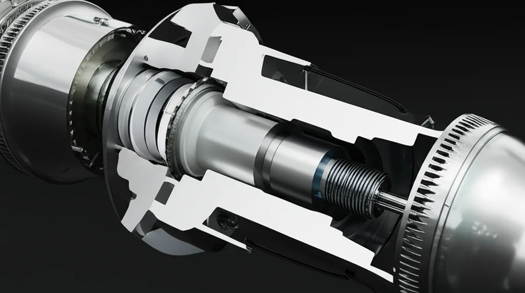
Engineering the H10: A Hot Topic, Coolly Handled
Before diving into the H10 design, we did some risk-reduction experiments with its predecessor, the H9 Hall thruster, back in 2022. We pushed it hard, looking at performance and stability under high power density and high voltage. The results were super encouraging! We hit 3,000 s specific impulse at 12 kW, and even ran the H9 up to 25 kW for short bursts – that’s 2.8 times higher power density than the state-of-the-art (SOTA)! Most importantly, we didn’t see any scary plasma instabilities or performance drops that would stop us from building the H10. Assuming magnetic shielding would keep it alive even at these high power densities, the H9 results basically turned the H10 design into a thermal engineering puzzle: how do we manage all that heat?
And manage it we did! The H10 design overachieved, allowing us to demonstrate thermal steady-state operation up to 15 kW (a 50% margin on our design goal) using only passive heat rejection – no fancy pumps or anything. Our results even suggest it could handle up to 20 kW, which is like 4 times SOTA power densities! So, what’s the secret sauce?
The H10 isn’t just an evolution; it’s a bit of a revolution. Key features include:
- A plasma lens magnetic field topography for top-notch performance.
- Of course, magnetic shielding for that crucial long life.
- A clever non-linear flux-balancing magnetic circuit that gives us high field strength without bulking up.
- Super high-uniformity gas injection.
- An integrated anode, gas distributor, and discharge chamber assembly all made from graphite. This is a big one for thermal management because it improves contact conductance, thermal conductivity, and how well it radiates heat.
- A multi-zone, passive thermal management system. This is super smart: it manages heat from different parts of the thruster (discharge chamber, inner magnetic bits, outer magnetic bits) separately, each with its own radiator. This keeps sensitive components cool.
- A centrally-mounted, heaterless LaB6 hollow cathode. This little guy is tough, capable of producing 50 A of discharge current for 25,000 hours! And it starts without a traditional heater, using a cool new tantalum-tube ignitor tech.
- It’s also impressively lightweight, around 20 kg (that’s 2 kg/kW at 10 kW).
This integrated graphite discharge chamber and the segmented passive cooling are what really let the H10 operate at such high power densities. Traditional Hall thrusters often use ceramics like boron nitride for the chamber walls, which aren’t great at conducting heat. Our graphite approach is a game-changer here.
The H10 Cathode: Starting Strong
Let’s geek out a bit on the H10 cathode. It’s a scaled-up version of the “lollipop” concept we used in the MaSMi Hall thruster. It’s compact, houses a Lanthanum Hexaboride (LaB6) thermionic insert (the bit that emits electrons), a graphite keeper electrode, and built-in heat shielding. It’s designed to be inserted from the downstream side and clamped securely. According to our models, this cathode can pump out 50 A for 25,000 hours, and even longer at lower currents. For its nominal 10 kW operation at 300 V, it’ll need 33 A, and it can do that for over 75,000 hours! That’s some serious stamina.
And it’s heaterless! It uses a nifty tantalum-tube ignitor. We apply 1 kV to the keeper with some xenon gas flowing, and a small Paschen discharge starts between the keeper and a tantalum gas feed tube. This heats the tantalum tube, which then radiatively heats the LaB6 insert. After about 3 minutes, the LaB6 takes over, the tantalum tube cools down, and we’re good to go. We tested a prototype of this cathode, and it happily ran from 5 to 50 A. During the H10 thruster tests, this cathode started up over 60 times without a single hiccup. Pretty neat, huh?

Putting H10 Through Its Paces
Once assembled, we took the H10 to the Owens Chamber at JPL for a serious workout. This chamber is a beast – 3 meters in diameter, 10 meters long, and cryogenically pumped to simulate the vacuum of space. We’ve tested thrusters up to 25 kW in there before. We had all sorts of gadgets to watch the H10: pressure gauges, a Residual Gas Analyzer (RGA) to check background gases, still and video cameras, a FLIR infrared camera to monitor temperatures, 18 thermocouples dotted around the thruster, and a Faraday probe to measure the ion current density in the plume.
Power and propellant (research-grade xenon) were supplied by commercial units. We had a robust electrical setup with high-speed voltage and current sensors to catch every detail of the plasma discharge. Thrust was measured using a super-sensitive, water-cooled, inverted-pendulum thrust stand. We’re talking an uncertainty of about ±1% for thrust, which is pretty darn good.
The test campaign was all about characterizing performance, stability, and thermal behavior. We ran it on xenon from 150-800 V and 0.2-20 kW. We even tried krypton propellant up to 12 kW. First things first, we outgassed the thruster for three days. Then, the moment of truth: ignition! The cathode lit up, and the thruster fired on the very first attempt at 150 V, 0.6 kW. By the end of day one, we were already at 300 V, 5 kW. We did have one minor hiccup – a loss of high-voltage isolation inside the thruster – which needed a quick repair. But over about 75 hours of operation and 60 cathode ignitions spanning two months, that was the only issue. Not bad for a brand-new design!
Visual checks and ion current density measurements confirmed the plume was nice and uniform. The ion current density profile showed a characteristic double peak, meaning the plume was well-focused. This is exactly what we want to see.
Performance That Wows
So, how did it do? In a word: fantastically! We measured thrust, specific impulse, and efficiency across a wide range of conditions. At most points, we tweaked the magnetic field to try and optimize performance, usually by minimizing discharge current, though we didn’t have time for a super systematic optimization. The cathode flow fraction (how much gas goes through the cathode vs. the main discharge) was also varied a bit, between 5-7%.
The peak performance on xenon was at 800 V, 10 kW, where the H10 produced 457 mN of thrust, a specific impulse of 3,400 seconds, and an efficiency of 76% with a cathode flow fraction of 5.1%. That 76% efficiency is, as far as we know, the highest ever recorded for a xenon Hall thruster, shielded or not! That’s something to write home about.
Compared to other thrusters, the H10 holds its own and then some. At 800 V, 9 kW, it gives 3,000 s Isp at 60% efficiency, very similar to the H9C. And at 600 V, 12 kW, it hits 3,050 s Isp at 71% efficiency, while the AEPS thruster (a current state-of-the-art system) gives 2,780 s Isp at 68% efficiency. So, we got all this improved thermal performance and lighter weight without sacrificing raw performance. Sweet!
We also looked at discharge current oscillations. Generally, they were less than 100% of the mean current, except around 6.25 A where we saw a peak across all voltages – that “stability barrier” we talked about earlier. Power spectral density analysis showed the typical modes we see in magnetically shielded Hall thrusters: a “breathing mode” below 27 kHz and a cathode-related mode between 83-100 kHz at 10 kW.

One of the most critical tests was demonstrating thermal steady-state operation. We ran the H10 for hours on end. We did a long run at 300 V, 10 kW, then another at 800 V, 10 kW, and finally at 600 V, first at 12 kW and then ramping up to 15 kW. The thruster was incredibly stable. The radiators got up to 200-260°C, and the backplate hit 370-400°C, but the area with wiring and propellant connections stayed below 150°C – well within limits for space-rated hardware. It took about 6-8 hours to reach steady state from a cold start, which is typical. Hitting 15 kW at steady state gives us a 50% power margin over our 10 kW design goal. We even briefly ran it up to 20 kW, and the data suggests it could probably handle that at steady state too, which would mean an incredible 100:1 power throttling ratio!
Why the H10 is a Big Deal
The H10’s ability to operate at high power density is what unlocks its amazing capabilities. It allows for a 2:1 power throttling ratio (5-10 kW) at 800 V (around 3,000 s specific impulse). Compared to its 10 kW operation, it maintains over 50% thrust efficiency over a 6:1 power throttling ratio and boasts a total power throttling ratio of 50:1 (and potentially up to 75:1 or 100:1!). This is huge because, without this high-density operation, magnetically shielded thrusters hit those plasma instabilities when you try to reduce current, forcing you to drop voltage and thus specific impulse.
And it’s light! At 20 kg, it’s significantly lighter than the 53 kg AEPS thruster. This reduced mass, parts count, and ultimately cost, is a direct result of decoupling thermal management from structural elements.
This design is also perfect for commercial applications, like in geosynchronous Earth orbit (GEO). A GEO mission often wants high thrust at max power for orbit raising, then high specific impulse at lower power for stationkeeping. The H10 can do, say, 300 V, 10 kW for orbit raising and then switch to 800 V, 5 kW for stationkeeping. And the design can easily be scaled for different power levels.
We’re assuming that the magnetic shielding will provide the long life (>10,000 hours) we need, even at these higher power densities. It’s important to note that the H10 is a high power density thruster, not necessarily a crazy high current density one, which is a different approach some are taking that might lead to erosion issues. We’re still a ways off from the absolute records in power density shown decades ago, and even further from theoretical limits, but we’re pushing!
JPL’s H10 Hall thruster, with its enhanced radiative heat rejection, integrated discharge chamber, and clever multi-zone passive thermal management, is a real step forward. This was just the first test campaign, and we’re already looking at ways to push power density even higher – maybe 10 times SOTA – using novel materials, additive manufacturing, and oscillating heat pipes. Imagine a megawatt-class thruster the size of older, much less powerful designs! That would radically cut down the mass and area needed for future high-power propulsion systems.
The H10 and technologies like it have massive potential for NASA. Think robotic sample return missions needing high Isp and long life affordably, or Nuclear Electric Propulsion (NEP) systems for human Mars missions. These future NEP systems will need such high specific impulse (over 3,000 s) and will likely use propellants more abundant than xenon, like argon or bismuth. The H10 is paving the way for this next generation of low-mass, high-Isp Hall thrusters, ready to take us further into the solar system.

Source: Springer