Bronze, Gears, and Guts: What Really Makes Your Worm Drive Tick?
Hey there, gearheads and material enthusiasts! Ever wondered what makes those trusty worm gear drives in everything from your car’s steering to massive industrial conveyors just… work? Well, a big part of the magic comes down to the materials, especially the bronze in the worm wheel. I’ve been digging into what makes these bronzes tick, and let me tell you, it’s more complex than just picking an alloy off a shelf.
The Current State of Play: Good, But We Can Do Better!
Right now, if you’re designing a worm gear, you’d probably look at standards like ISO/TS 14521. These are super helpful, no doubt, but when it comes to predicting wear on that bronze worm wheel, they mostly look at the alloy and how it was cast. It’s a good starting point, but it’s a bit like judging a book by its cover, or maybe its publisher, rather than what’s actually written inside. You know what I mean? The real story is often hidden in the details.
The Microstructure Mystery: It’s What’s Inside That Counts
You see, even if you use the exact same bronze recipe (like the popular CuSn12Ni2) and the same casting method, the actual microscopic structure – the microstructure – can be pretty different. Things like the specific casting parameters and even the size of the gear play a huge role. And this microstructure? It’s a massive deal for how well the gear resists wear. So, if we want to get really good at predicting wear and making even better gears, we need to get up close and personal with these bronze microstructures.
Our Mission: Getting to Know Bronze, Intimately
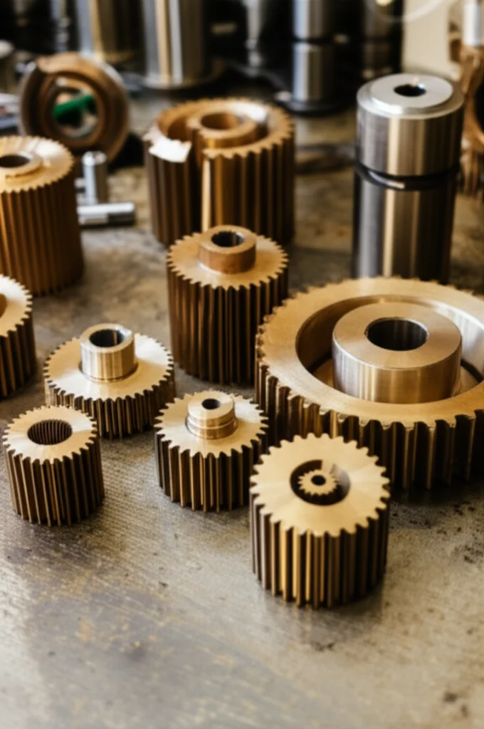
That’s what I’ve been up to! We’ve taken a fresh look at a whole bunch of material samples – from 50 different worm wheels used in past research projects, some dating back to the 90s! Talk about a treasure trove. Our goal is to really understand what’s going on at a micro-level. We’re specifically looking at two main things:
- Grain size: Think of it like the tiny crystals that make up the metal. We measure this according to a standard called ASTM E112-13.
- The δ-phase (delta-phase): This is a specific component within the bronze’s structure, and we check its proportion using a guideline known as BDG 771.
Most of the wheels we looked at are made of CuSn12Ni2 bronze, produced by three main casting methods: centrifugal casting (GZ), continuous casting (GC), and a special heat-treated continuous casting (GCB). Each has its own quirks, as we’ll see!
What’s in a Bronze Worm Wheel, Anyway?
So, why CuSn12Ni2? Well, it’s a bit of a star in the worm gear world because it’s pretty tough against corrosion and wear. When you polish up a sample and look under a microscope, you see this cool, somewhat mixed-up structure. There’s a softer main part called the α-phase (alpha-phase), which is basically tin dissolved in copper. Then, there are harder bits called the δ-phase (delta-phase), an intermetallic compound (Cu31Sn8, if you want to get technical!).
The α-phase is softer (around 154 HV), while the δ-phase is much harder (around 415 HV). The theory is, the more of that hard δ-phase you have, and the more evenly it’s spread out, the better your gear will resist wear. It’s like having tiny, super-hard reinforcements scattered throughout the material – pretty neat, right?
Casting Call: Meet GZ, GC, and GCB
How these phases arrange themselves depends a lot on how the bronze is cast. It’s not just about pouring metal into a mold; it’s an art and a science!
- Centrifugal Casting (GZ): Imagine pouring molten bronze into a spinning mold. The centrifugal force squashes everything together, leading to a dense, uniform structure. This is great for larger worm wheels, but it has its limits for smaller ones.
- Continuous Casting (GC): This is more suited for smaller gears. Molten metal is cooled in a graphite mold as more melt is added from above. This can sometimes lead to larger grains because of how the crystals form during the cooling process.
- Heat-Treated Continuous Casting (GCB): This is a bit of a special one. It’s a patented process that aims to get the fine, uniform structure you see in centrifugal casting, but using a continuous process. Pretty clever, huh? It’s all about getting the best of both worlds.
Lots of smart folks have studied these bronzes, looking at everything from pitting (those annoying little surface craters) to friction. But one thing that’s often missing is a good understanding of how much the material properties can vary just because of the nitty-gritty of the manufacturing process. That’s where our big database of 50 worm wheels comes in handy! We’re looking for patterns that others might have missed.
Wear and Tear: The Standard Approach vs. What Really Happens
Current standards, like ISO/TS 14521, calculate wear using factors that are mostly tied to the casting method. So, a centrifugally cast (GZ) wheel gets one factor, and a continuously cast (GC) wheel gets another. This is an indirect way of guessing the microstructure, but it’s the microstructure itself, not just the casting label, that really dictates wear. It’s like saying all cars from one factory are identical, but we know there are always subtle differences!
Research has shown this time and again. For example, studies by Moshkovich and others found that larger grain sizes can lead to more wear. Others, like Stella and Sievers, showed that GCB bronze (with its smaller grains) can be more wear-resistant than GC, and that even with the same GZ casting, different parameters can give you different microstructures and thus different wear behavior. A higher amount of that hard δ-phase? Generally means less wear. Smaller grains? Also good for wear resistance. It’s all connected!

Digging Deeper: Our Re-evaluation Mission
So, we decided it was time to really get to grips with this. We pulled out microsections from those 50 worm wheels – some from way back in 1990! We’re talking CuSn12Ni2 made by GZ, GC, and GCB methods. These wheels varied in size (we use ‘centre distance’ as a proxy for size), casting method, and even the specific batch they came from. It was like an archaeological dig, but for gear materials!
Our Detective Work: How We Measured the Guts of a Gear
For each wheel, we looked at microsections, usually cut radially from the tooth tip down towards the root. This gives us a cross-section view of what’s happening inside.
- Finding the δ-phase: We’d polish a sample until it shone, take a picture under the microscope, and then use a software tool to highlight and measure the area covered by the δ-phase. It’s a bit like coloring in the hard bits to see how much there is. Precision is key here!
- Sizing Up the Grains: After checking the δ-phase, we’d etch the same sample with a special chemical (KLEMM-III, if you’re curious) to make the grain boundaries visible. Then, using a method called the ‘linear intercept procedure’ (from ASTM E112-13), we’d draw lines across the image, count how many grains each line crossed, and from that, calculate an average grain size. It sounds tedious, and it is, but the data is golden!
We did this for about 700 microsections across the 50 wheels! We even checked multiple teeth on many wheels to get a feel for how consistent the microstructure was. And good news: the structure inside the tooth (where we measured) is pretty much the same as on the surface where the wear actually happens. So, our method is solid for understanding what influences wear. Phew!
The Results Are In! Part 1: The δ-Phase Story
Alright, let’s talk about what we found, starting with that all-important δ-phase. This is where things get juicy!
A Look Across Casting Types
For centrifugally cast (GZ) bronze, the δ-phase proportion danced between 2.5% and 14%. For heat-treated continuous cast (GCB) bronze, it was a similar story, ranging from 2.5% to 12%. (We only had one good set of GC samples for δ-phase, so we’ll touch on that a bit later). This shows there’s quite a bit of natural variation out there.
Zooming In: A Tale of Two Gears
To really see how the δ-phase varied within a single wheel, we took a super close look at two GCB gears (we called them Gear 20 and Gear 21, both for a 65mm centre distance). We analyzed 6 different segments around the circumference and 8 spots radially down each tooth.
What did we see? Well, mostly, the δ-phase proportion was pretty similar around the gear. But here’s a cool trend: as we moved from the tip of the tooth down towards the root, the amount of δ-phase tended to increase. For these two gears, it went from about 5.0% at the tip to 6.5% at a 10.5mm depth. This tells us that where you take your sample matters! It’s not just one number for the whole gear.
δ-Phase and Gear Size: What’s the Connection?
We then crunched all the numbers to see if we could predict the δ-phase based on the casting process and the gearbox size (using centre distance). We calculated mean values and 95% confidence intervals – fancy stats to tell us how sure we are.
Generally, it looks like the proportion of δ-phase tends to be a bit higher in smaller gear sizes and, as we saw, in sections closer to the gear’s center or tooth root. However, there wasn’t a super strong, clear-cut trend linking δ-phase directly to overall gear size across all casting types. It’s a bit more nuanced than that, with a fair bit of scatter in the values, which is typical in real-world materials.
The Results Are In! Part 2: The Grain Size Saga
Now, let’s switch gears (pun intended!) to grain size. Remember, smaller is often better for wear, giving the material more toughness.
General Trends
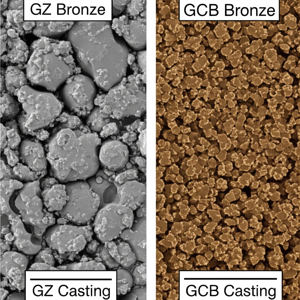
Looking at the averages for each wheel, we immediately saw something interesting: GCB bronze generally had smaller grains than GZ bronze. And for the few GC samples we had, the grains were, frankly, enormous in comparison! This was a big “aha!” moment.
Deep Dive: Gears 20 e 21 Again
Using our detailed analysis of Gears 20 and 21 (the GCB ones), we saw a similar radial trend for grain size as we did for δ-phase: grain size tended to increase as we moved from the tooth tip towards the tooth root. Again, the variation around the circumference wasn’t huge, but that radial change was noticeable. Consistency is good, but understanding variation is better!
Grain Size, Casting, and Gear Size: The Big Picture
This is where things got really interesting. When we looked at all the data, grouping by casting process and centre distance:
- Continuous Casting (GC): Whoa! The grain sizes here were significantly larger. For a 50mm centre distance, GC bronze had an average grain size around 1510 µm (that’s 1.5 millimeters!). Compare that to GCB at the same size, which was about 31.8 µm – a massive difference!
- Heat-Treated Continuous Casting (GCB): This process consistently produced smaller grains. And here’s a key finding: as the gear size (centre distance) increased, the average grain size also tended to increase. For example, at a 32mm centre distance, the 95% confidence interval for grain size was 24.8-26.9 µm. At 100mm, it was 56.9-62.3 µm. Size matters!
- Centrifugal Casting (GZ): GZ generally had larger grains than GCB for comparable sizes. For instance, at a 100mm centre distance, GZ grains were in the 93.9-111.8 µm range, while GCB was, as mentioned, 56.9-62.3 µm. GZ also showed the trend of increasing grain size with increasing gear size.
This is a big deal! It means that just saying “it’s GZ bronze” isn’t enough. The size of the gear itself influences the grain structure you end up with. It’s like baking – a small cake and a giant cake made with the same recipe won’t bake exactly the same way.

So, What Does This All Mean for My Worm Gears?
Okay, we’ve waded through a lot of data on δ-phases and grain sizes. My head is spinning a bit too! What are the big takeaways for anyone working with or relying on these gears?
Microstructure Isn’t Uniform – Expect Variation!
First off, the microstructure within a single bronze worm wheel isn’t perfectly the same everywhere. Both the δ-phase proportion and the grain size tend to increase slightly as you go from the tooth tip down towards the tooth root. The δ-phase trend was a bit weak for GZ bronze, but generally, it’s something to keep in mind. If you’re taking samples for quality control or research, where you take them from matters! We’d recommend analyzing at least a couple of teeth to get a good overall picture because there’s always a bit of natural scatter. Nature isn’t perfectly neat!
Casting Process e Gear Size are BFFs for Grains
When it comes to grain size, the story is clearer:
- GC (Continuous Casting) generally gives you the largest grains. Not always ideal if you’re chasing wear resistance.
- GZ (Centrifugal Casting) comes in next, with more moderate grain sizes.
- GCB (Heat-Treated Continuous Casting) tends to produce the smallest grains, especially when compared to GC. For the sizes we looked at (65mm and 100mm centre distances), GCB had smaller grains than GZ. This makes GCB look pretty attractive!
Crucially, we saw a clear trend: the bigger the worm wheel, the bigger the average grain size in the tooth area, regardless of the specific GZ or GCB casting process. This is super important because it suggests that current design standards, like ISO/TS 14521, might need a little tweak. Right now, they don’t really account for gear size affecting the material’s intrinsic properties this way. If bigger gears have bigger grains, and bigger grains can mean more wear (as other research suggests), then maybe larger gears (especially those with centre distances over, say, 50mm) should be designed with a bit more caution or a different material factor.
The δ-Phase Picture: A Bit More Complex
For the δ-phase, the link to overall gear size wasn’t as clear-cut as it was for grain size. GCB bronze did tend to have a higher proportion of δ-phase than GC bronze, which is generally a good thing for hardness and wear.
Towards Smarter Gear Design: The Future is Micro!
So, what’s the ultimate goal here? We’re trying to get to a point where we can more accurately predict how a worm gear will wear based on its actual microstructure, not just its casting method label. It’s about getting specific!
Knowing these typical ranges for grain size and δ-phase for different casting processes and gear sizes is a fantastic first step. Previous research strongly suggests that a finer grain structure and a higher amount of the hard δ-phase are good things for wear resistance. It’s like having a well-built team of tiny defenders in your material.
It might be time to think about refining that material-lubricant factor (WML) in ISO/TS 14521. Perhaps it could be adjusted based on the expected grain size for a given material, casting process, AND gear size. Of course, more experiments are needed to nail that down, but it’s an exciting direction.
Making a sweeping statement like “this casting process is always best” is tough. Each has its pros and cons depending on the application and gear size. But if you’re aiming for top-notch wear resistance, you’d ideally want a process that gives you fine grains and plenty of that lovely δ-phase.
This work is all about pushing towards a more material-savvy approach to designing worm gears. The more we understand about these amazing bronze materials, the better, stronger, and longer-lasting our gear drives will be! It’s a journey, but every bit of data helps us get a clearer picture. And hopefully, it helps you appreciate the incredible engineering that goes into even the seemingly simplest components!
Source: Springer


